-
 Agriculture
-
 Health-Care
-
 Environment
-
 Construction-Real-Estate
-
 Tools-Hardware
-
 Home-Garden
-
 Furniture
-
 Luggage-Bags-Cases
-
 Medical-devices-Supplies
-
 Gifts-Crafts
-
 Sports-Entertainment
-
 Food-Beverage
-
 Vehicles-Transportation
-
 Power-Transmission
-
 Material-Handling
-
 Renewable-Energy
-
 Safety
-
 Testing-Instrument-Equipment
-
 Construction-Building-Machinery
-
 Pet-Supplies
-
 Personal-Care-Household-Cleaning
-
 Vehicle-Accessories-Electronics-Tools
-
 School-Office-Supplies
-
 Packaging-Printing
-
 Mother-Kids-Toys
-
 Business-Services
-
 Commercial-Equipment-Machinery
-
 Apparel-Accessories
-
 Security
-
 Shoes-Accessories
-
 Vehicle-Parts-Accessories
-
 Jewelry-Eyewear-Watches-Accessories
-
 Lights-Lighting
-
 Fabric-Textile-Raw-Material
-
 Fabrication-Services
-
 Industrial-Machinery
-
 Consumer-Electronics
-
 Electrical-Equipment-Supplies
-
 Electronic-Components-Accessories-Telecommunications
-
 Home-Appliances
-
 Beauty
-
 Chemicals
-
 Rubber-Plastics
-
 Metals-Alloys
- Masonry Materials
- Curtain Walls & Accessories
- Earthwork Products
- Fireproofing Materials
- Heat Insulation Materials
- Plastic Building Materials
- Building Boards
- Soundproofing Materials
- Timber
- Waterproofing Materials
- Balustrades & Handrails
- Bathroom & Kitchen
- Flooring & Accessories
- Tiles & Accessories
- Door, Window & Accessories
- Fireplaces & Stoves
- Floor Heating Systems & Parts
- Stairs & Stair Parts
- Ceilings
- Elevators & Escalators
- Stone
- Countertops, Vanity Tops & Table Tops
- Mosaics
- Metal Building Materials
- Multifunctional Materials
- Ladders & Scaffoldings
- Mouldings
- Corner Guards
- Decorative Films
- Formwork
- Building & Industrial Glass
- Other Construction & Real Estate
- Wallpapers/Wall panels
- HVAC System & Parts
- Outdoor Facilities
- Prefabricated Buildings
- Festive & Party Supplies
- Bathroom Products
- Household Sundries
- Rain Gear
- Garden Supplies
- Household Cleaning Tools & Accessories
- Lighters & Smoking Accessories
- Home Storage & Organization
- Household Scales
- Smart Home Improvement
- Home Textiles
- Kitchenware
- Drinkware & Accessories
- Dinnerware, Coffee & Wine
- Home Decor
- Golf
- Fitness & Body Building
- Amusement Park Facilities
- Billiards, Board Game,Coin Operated Games
- Musical Instruments
- Outdoor Affordable Luxury Sports
- Camping & Hiking
- Fishing
- Sports Safety&Rehabilitation
- Ball Sports Equipments
- Water Sports
- Winter Sports
- Luxury Travel Equipments
- Sports Shoes, Bags & Accessories
- Cycling
- Other Sports & Entertainment Products
- Artificial Grass&Sports Flooring&Sports Court Equipment
- Scooters
- Food Ingredients
- Honey & Honey Products
- Snacks
- Nuts & Kernels
- Seafood
- Plant & Animal Oil
- Beverages
- Fruit & Vegetable Products
- Frog & Escargot
- Bean Products
- Egg Products
- Dairy Products
- Seasonings & Condiments
- Canned Food
- Instant Food
- Baked Goods
- Other Food & Beverage
- Meat & Poultry
- Confectionery
- Grain Products
- Feminie Care
- Hair Care & Styling
- Body Care
- Hands & Feet Care
- Hygiene Products
- Men's Grooming
- Laundry Cleaning Supplies
- Travel Size & Gift Sets
- Room Deodorizers
- Other Personal Care Products
- Pest Control Products
- Special Household Cleaning
- Floor Cleaning
- Kitchen & Bathroom Cleaning
- Oral Care
- Bath Supplies
- Yellow Pages
- Correction Supplies
- Office Binding Supplies
- Office Cutting Supplies
- Board Erasers
- Office Adhesives & Tapes
- Education Supplies
- Pencil Cases & Bags
- Notebooks & Writing Pads
- File Folder Accessories
- Calendars
- Writing Accessories
- Commercial Office Supplies
- Pencil Sharpeners
- Pens
- Letter Pad/Paper
- Paper Envelopes
- Desk Organizers
- Pencils
- Markers & Highlighters
- Filing Products
- Art Supplies
- Easels
- Badge Holder & Accessories
- Office Paper
- Printer Supplies
- Book Covers
- Other Office & School Supplies
- Stationery Set
- Boards
- Clipboards
- Stamps
- Drafting Supplies
- Stencils
- Electronic Dictionary
- Books
- Map
- Magazines
- Calculators
- Baby & Toddler Toys
- Educational Toys
- Classic Toys
- Dress Up & Pretend Play
- Toy Vehicle
- Stuffed Animals & Plush Toys
- Outdoor Toys & Structures
- Balloons & Accessories
- Baby Food
- Children's Clothing
- Baby Supplies & Products
- Maternity Clothes
- Kids Shoes
- Baby Care
- Novelty & Gag Toys
- Dolls & Accessories
- Puzzle & Games
- Blocks & Model Building Toys
- Toddler Clothing
- Baby Clothing
- Kids' Luggage & Bags
- Arts, Crafts & DIY Toys
- Action & Toy Figures
- Baby Appliances
- Hobbies & Models
- Remote Control Toys
- Promotional Toys
- Pregnancy & Maternity
- Hygiene Products
- Kid's Textile&Bedding
- Novelty & Special Use
- Toy Weapons
- Baby Gifts
- Baby Storage & Organization
- Auto Drive Systems
- ATV/UTV Parts & Accessories
- Marine Parts & Accessories
- Other Auto Parts
- Trailer Parts & Accessories
- Auto Transmission Systems
- Train Parts & Accessories
- Universal Parts
- Railway Parts & Accessories
- Auto Brake Systems
- Aviation Parts & Accessories
- Truck Parts & Accessories
- Auto Suspension Systems
- Auto Lighting Systems
- New Energy Vehicle Parts & Accessories
- Auto Steering Systems
- Wheels, Tires & Accessories
- Bus Parts & Accessories
- Auto Performance Parts
- Cooling System
- Go-Kart & Kart Racer Parts & Accessories
- Air Conditioning Systems
- Heavy Duty Vehicle Parts & Accessories
- Auto Electrical Systems
- Auto Body Systems
- Auto Engine Systems
- Container Parts & Accessories
- Motorcycle Parts & Accessories
- Refrigeration & Heat Exchange Equipment
- Machine Tool Equipment
- Food & Beverage Machinery
- Agricultural Machinery & Equipment
- Apparel & Textile Machinery
- Chemical Machinery
- Packaging Machines
- Paper Production Machinery
- Plastic & Rubber Processing Machinery
- Industrial Robots
- Electronic Products Machinery
- Metal & Metallurgy Machinery
- Woodworking Machinery
- Home Product Manufacturing Machinery
- Machinery Accessories
- Environmental Machinery
- Machinery Service
- Electrical Equipment Manufacturing Machinery
- Industrial Compressors & Parts
- Tobacco & Cigarette Machinery
- Production Line
- Used Industrial Machinery
- Electronics Production Machinery
- Other Machinery & Industrial Equipment
- Camera, Photo & Accessories
- Portable Audio, Video & Accessories
- Television, Home Audio, Video & Accessories
- Video Games & Accessories
- Mobile Phone & Accessories
- Electronic Publications
- Earphone & Headphone & Accessories
- Speakers & Accessories
- Smart Electronics
- TV Receivers & Accessories
- Mobile Phone & Computer Repair Parts
- Chargers, Batteries & Power Supplies
- Used Electronics
- VR, AR, MR Hardware & Software
- Projectors & Presentation Equipments
- Other Consumer Electronics
- Cables & Commonly Used Accessories
- Computer Hardware & Software
- Displays, Signage and Optoelectronics
- Discrete Semiconductors
- Wireless & IoT Module and Products
- Telecommunications
- Connectors, Terminals & Accessories
- Development Boards, Electronic Modules and Kits
- Circuit Protection
- Sensors
- Isolators
- Audio Components and Products
- Integrated Circuits
- Power Supplies
- Relays
- RF, Microwave and RFID
- Electronic Accessories & Supplies
- Passive Components
- PCB & PCBA
- Air Quality Appliances
- Home Appliance Parts
- Heating & Cooling Appliances
- Small Kitchen Appliances
- Laundry Appliances
- Water Heaters
- Water Treatment Appliances
- Refrigerators & Freezers
- Personal Care & Beauty Appliances
- Major Kitchen Appliances
- Cleaning Appliances
- Second-hand Appliances
- Smart Home Appliances
- Other Home Appliances
- Energy Chemicals
- Inorganic Chemicals
- Basic Organic Chemicals
- Agrochemicals
- Admixture & Additives
- Catalysts & Chemical Auxiliary Agents
- Pigments & Dyestuff
- Coating & Paint
- Daily Chemicals
- Polymer
- Organic Intermediate
- Adhesives & Sealants
- Chemical Waste
- Biological Chemical Products
- Surface Treatment Chemicals
- Painting & Coating
- Chemical Reagents
- Flavor & Fragrance
- Non-Explosive Demolition Agents
- Other Chemicals
- Custom Chemical Services
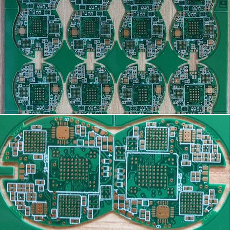
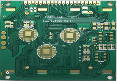
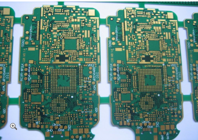
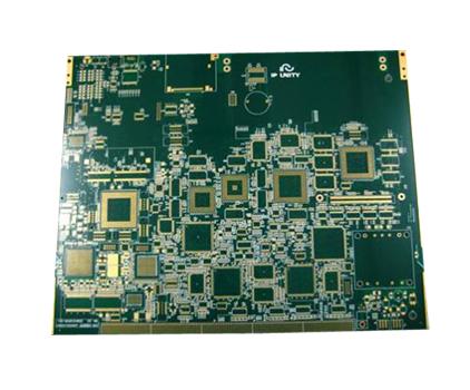
Advanced Video Network Transmission Card PCB Layout Optimized for Stable Connectivity
In today's rapidly evolving digital landscape, the demand for high-quality video transmission over networks has surged, driven by applications ranging from live streaming and video conferencing to surveillance and broadcasting. At the heart of this technological advancement lies the Advanced Video Network Transmission Card, a critical component that ensures seamless data flow. However, its performance hinges on the precision of its Printed Circuit Board (PCB) layout, which must be optimized for stable connectivity to prevent issues like signal degradation, latency, and data loss. This article delves into the intricacies of designing such a PCB, highlighting how strategic layout techniques can enhance reliability and efficiency, ultimately captivating engineers and tech enthusiasts by showcasing the fusion of innovation and practicality in modern electronics.
To set the stage, video network transmission cards handle high-bandwidth data streams, often in real-time, making them susceptible to electromagnetic interference (EMI), crosstalk, and thermal challenges. A poorly designed PCB can lead to unstable connections, resulting in distorted video quality or system failures. By focusing on optimized layouts, manufacturers can achieve robust performance, meeting the rigorous demands of industries like telecommunications and entertainment. This exploration will cover key aspects, including signal integrity management, power distribution, thermal considerations, and material selection, providing a comprehensive guide for those involved in electronic design and network infrastructure.
Signal Integrity and Impedance Control
Maintaining signal integrity is paramount in the PCB layout of an advanced video network transmission card, as it directly impacts the stability of data transmission. Video signals, especially those in high-definition formats, operate at high frequencies where even minor disruptions can cause significant distortions. To address this, designers employ controlled impedance routing, which ensures that the characteristic impedance of transmission lines matches the source and load impedances. This minimizes reflections and signal loss, preserving the clarity and accuracy of video data. For instance, differential pairs used in interfaces like HDMI or Ethernet require precise spacing and length matching to maintain signal balance and reduce electromagnetic interference.
Furthermore, the use of ground planes and shielding techniques plays a crucial role in safeguarding signal paths. By placing continuous ground layers beneath signal traces, the PCB can provide a low-impedance return path, reducing noise and crosstalk between adjacent lines. Additionally, strategic via placement and minimizing stub lengths help in maintaining signal quality across layers. In high-speed designs, simulations using tools like SPICE or electromagnetic field solvers are often conducted to predict and mitigate potential issues before fabrication. This proactive approach ensures that the video transmission card can handle bandwidth-intensive applications without compromising on connectivity stability, making it ideal for environments where reliability is non-negotiable.
Power Distribution Network Design
A robust power distribution network (PDN) is essential for the stable operation of an advanced video network transmission card, as voltage fluctuations or noise can lead to intermittent connectivity and performance degradation. The PCB layout must incorporate a well-designed PDN to deliver clean and consistent power to all components, such as processors, memory, and transceivers. This begins with the use of multiple power planes and decoupling capacitors placed close to IC pins. These capacitors act as local energy reservoirs, smoothing out transient currents and suppressing high-frequency noise that could otherwise interfere with signal integrity.
Moreover, the strategic routing of power traces involves minimizing loop areas to reduce inductance and electromagnetic emissions. Designers often employ star routing or split planes to isolate analog and digital sections, preventing noise coupling between them. For high-current paths, wider traces and thermal vias are integrated to enhance current-carrying capacity and dissipate heat effectively. By optimizing the PDN through careful simulation and layout practices, the PCB can maintain stable voltage levels even under varying loads, ensuring that the video transmission card operates reliably in network-intensive scenarios. This not only boosts connectivity but also extends the lifespan of the card by reducing stress on sensitive components.
Thermal Management Strategies
Effective thermal management is critical in the PCB layout of an advanced video network transmission card, as excessive heat can compromise component performance and lead to unstable connectivity. Video processing chips and network interfaces generate significant heat during operation, which, if not dissipated properly, can cause thermal throttling or permanent damage. To mitigate this, the PCB design incorporates thermal vias, heat sinks, and copper pours that facilitate efficient heat transfer away from hot spots. For example, placing thermal vias under high-power components like FPGAs or GPUs helps conduct heat to inner layers or the opposite side of the board, where it can be managed by external cooling solutions.
Additionally, the layout considers airflow and component placement to avoid thermal bottlenecks. By spacing out heat-generating elements and orienting them in the direction of natural or forced convection, the design promotes even temperature distribution. Materials with high thermal conductivity, such as metal-core PCBs or specialized substrates, may be used in extreme cases to enhance heat dissipation. Through thermal simulation software, designers can model heat flow and identify potential issues early in the process. This proactive thermal management ensures that the video transmission card maintains optimal performance under continuous operation, supporting stable network connectivity in demanding applications like data centers or broadcast studios.
Material Selection and Layer Stackup
The choice of materials and layer stackup in the PCB layout profoundly influences the stability and connectivity of an advanced video network transmission card. High-frequency video signals require substrates with low dielectric loss and consistent electrical properties to minimize attenuation and phase distortion. Materials like FR-4 with enhanced properties or specialized laminates such as Rogers or Isola are often selected for their superior performance at high speeds. These materials help maintain signal integrity by reducing dispersion and ensuring that impedance controls are effective across the entire board.
In terms of layer stackup, a well-planned configuration is vital for managing signal layers, power planes, and ground references. A typical stackup might include multiple signal layers sandwiched between ground planes to provide shielding and reduce EMI. For instance, a 6-layer or 8-layer stackup allows for dedicated layers for high-speed signals, power, and ground, minimizing crosstalk and improving return path continuity. The thickness and order of layers are optimized through impedance calculations to achieve the desired performance characteristics. By carefully selecting materials and designing the stackup, the PCB can support the high bandwidth requirements of video transmission while ensuring long-term reliability and stable connectivity in diverse network environments.
REPORT


