-
 Agriculture
-
 Health-Care
-
 Environment
-
 Construction-Real-Estate
-
 Tools-Hardware
-
 Home-Garden
-
 Furniture
-
 Luggage-Bags-Cases
-
 Medical-devices-Supplies
-
 Gifts-Crafts
-
 Sports-Entertainment
-
 Food-Beverage
-
 Vehicles-Transportation
-
 Power-Transmission
-
 Material-Handling
-
 Renewable-Energy
-
 Safety
-
 Testing-Instrument-Equipment
-
 Construction-Building-Machinery
-
 Pet-Supplies
-
 Personal-Care-Household-Cleaning
-
 Vehicle-Accessories-Electronics-Tools
-
 School-Office-Supplies
-
 Packaging-Printing
-
 Mother-Kids-Toys
-
 Business-Services
-
 Commercial-Equipment-Machinery
-
 Apparel-Accessories
-
 Security
-
 Shoes-Accessories
-
 Vehicle-Parts-Accessories
-
 Jewelry-Eyewear-Watches-Accessories
-
 Lights-Lighting
-
 Fabric-Textile-Raw-Material
-
 Fabrication-Services
-
 Industrial-Machinery
-
 Consumer-Electronics
-
 Electrical-Equipment-Supplies
-
 Electronic-Components-Accessories-Telecommunications
-
 Home-Appliances
-
 Beauty
-
 Chemicals
-
 Rubber-Plastics
-
 Metals-Alloys
- Masonry Materials
- Curtain Walls & Accessories
- Earthwork Products
- Fireproofing Materials
- Heat Insulation Materials
- Plastic Building Materials
- Building Boards
- Soundproofing Materials
- Timber
- Waterproofing Materials
- Balustrades & Handrails
- Bathroom & Kitchen
- Flooring & Accessories
- Tiles & Accessories
- Door, Window & Accessories
- Fireplaces & Stoves
- Floor Heating Systems & Parts
- Stairs & Stair Parts
- Ceilings
- Elevators & Escalators
- Stone
- Countertops, Vanity Tops & Table Tops
- Mosaics
- Metal Building Materials
- Multifunctional Materials
- Ladders & Scaffoldings
- Mouldings
- Corner Guards
- Decorative Films
- Formwork
- Building & Industrial Glass
- Other Construction & Real Estate
- Wallpapers/Wall panels
- HVAC System & Parts
- Outdoor Facilities
- Prefabricated Buildings
- Festive & Party Supplies
- Bathroom Products
- Household Sundries
- Rain Gear
- Garden Supplies
- Household Cleaning Tools & Accessories
- Lighters & Smoking Accessories
- Home Storage & Organization
- Household Scales
- Smart Home Improvement
- Home Textiles
- Kitchenware
- Drinkware & Accessories
- Dinnerware, Coffee & Wine
- Home Decor
- Golf
- Fitness & Body Building
- Amusement Park Facilities
- Billiards, Board Game,Coin Operated Games
- Musical Instruments
- Outdoor Affordable Luxury Sports
- Camping & Hiking
- Fishing
- Sports Safety&Rehabilitation
- Ball Sports Equipments
- Water Sports
- Winter Sports
- Luxury Travel Equipments
- Sports Shoes, Bags & Accessories
- Cycling
- Other Sports & Entertainment Products
- Artificial Grass&Sports Flooring&Sports Court Equipment
- Scooters
- Food Ingredients
- Honey & Honey Products
- Snacks
- Nuts & Kernels
- Seafood
- Plant & Animal Oil
- Beverages
- Fruit & Vegetable Products
- Frog & Escargot
- Bean Products
- Egg Products
- Dairy Products
- Seasonings & Condiments
- Canned Food
- Instant Food
- Baked Goods
- Other Food & Beverage
- Meat & Poultry
- Confectionery
- Grain Products
- Feminie Care
- Hair Care & Styling
- Body Care
- Hands & Feet Care
- Hygiene Products
- Men's Grooming
- Laundry Cleaning Supplies
- Travel Size & Gift Sets
- Room Deodorizers
- Other Personal Care Products
- Pest Control Products
- Special Household Cleaning
- Floor Cleaning
- Kitchen & Bathroom Cleaning
- Oral Care
- Bath Supplies
- Yellow Pages
- Correction Supplies
- Office Binding Supplies
- Office Cutting Supplies
- Board Erasers
- Office Adhesives & Tapes
- Education Supplies
- Pencil Cases & Bags
- Notebooks & Writing Pads
- File Folder Accessories
- Calendars
- Writing Accessories
- Commercial Office Supplies
- Pencil Sharpeners
- Pens
- Letter Pad/Paper
- Paper Envelopes
- Desk Organizers
- Pencils
- Markers & Highlighters
- Filing Products
- Art Supplies
- Easels
- Badge Holder & Accessories
- Office Paper
- Printer Supplies
- Book Covers
- Other Office & School Supplies
- Stationery Set
- Boards
- Clipboards
- Stamps
- Drafting Supplies
- Stencils
- Electronic Dictionary
- Books
- Map
- Magazines
- Calculators
- Baby & Toddler Toys
- Educational Toys
- Classic Toys
- Dress Up & Pretend Play
- Toy Vehicle
- Stuffed Animals & Plush Toys
- Outdoor Toys & Structures
- Balloons & Accessories
- Baby Food
- Children's Clothing
- Baby Supplies & Products
- Maternity Clothes
- Kids Shoes
- Baby Care
- Novelty & Gag Toys
- Dolls & Accessories
- Puzzle & Games
- Blocks & Model Building Toys
- Toddler Clothing
- Baby Clothing
- Kids' Luggage & Bags
- Arts, Crafts & DIY Toys
- Action & Toy Figures
- Baby Appliances
- Hobbies & Models
- Remote Control Toys
- Promotional Toys
- Pregnancy & Maternity
- Hygiene Products
- Kid's Textile&Bedding
- Novelty & Special Use
- Toy Weapons
- Baby Gifts
- Baby Storage & Organization
- Auto Drive Systems
- ATV/UTV Parts & Accessories
- Marine Parts & Accessories
- Other Auto Parts
- Trailer Parts & Accessories
- Auto Transmission Systems
- Train Parts & Accessories
- Universal Parts
- Railway Parts & Accessories
- Auto Brake Systems
- Aviation Parts & Accessories
- Truck Parts & Accessories
- Auto Suspension Systems
- Auto Lighting Systems
- New Energy Vehicle Parts & Accessories
- Auto Steering Systems
- Wheels, Tires & Accessories
- Bus Parts & Accessories
- Auto Performance Parts
- Cooling System
- Go-Kart & Kart Racer Parts & Accessories
- Air Conditioning Systems
- Heavy Duty Vehicle Parts & Accessories
- Auto Electrical Systems
- Auto Body Systems
- Auto Engine Systems
- Container Parts & Accessories
- Motorcycle Parts & Accessories
- Refrigeration & Heat Exchange Equipment
- Machine Tool Equipment
- Food & Beverage Machinery
- Agricultural Machinery & Equipment
- Apparel & Textile Machinery
- Chemical Machinery
- Packaging Machines
- Paper Production Machinery
- Plastic & Rubber Processing Machinery
- Industrial Robots
- Electronic Products Machinery
- Metal & Metallurgy Machinery
- Woodworking Machinery
- Home Product Manufacturing Machinery
- Machinery Accessories
- Environmental Machinery
- Machinery Service
- Electrical Equipment Manufacturing Machinery
- Industrial Compressors & Parts
- Tobacco & Cigarette Machinery
- Production Line
- Used Industrial Machinery
- Electronics Production Machinery
- Other Machinery & Industrial Equipment
- Camera, Photo & Accessories
- Portable Audio, Video & Accessories
- Television, Home Audio, Video & Accessories
- Video Games & Accessories
- Mobile Phone & Accessories
- Electronic Publications
- Earphone & Headphone & Accessories
- Speakers & Accessories
- Smart Electronics
- TV Receivers & Accessories
- Mobile Phone & Computer Repair Parts
- Chargers, Batteries & Power Supplies
- Used Electronics
- VR, AR, MR Hardware & Software
- Projectors & Presentation Equipments
- Other Consumer Electronics
- Cables & Commonly Used Accessories
- Computer Hardware & Software
- Displays, Signage and Optoelectronics
- Discrete Semiconductors
- Wireless & IoT Module and Products
- Telecommunications
- Connectors, Terminals & Accessories
- Development Boards, Electronic Modules and Kits
- Circuit Protection
- Sensors
- Isolators
- Audio Components and Products
- Integrated Circuits
- Power Supplies
- Relays
- RF, Microwave and RFID
- Electronic Accessories & Supplies
- Passive Components
- PCB & PCBA
- Air Quality Appliances
- Home Appliance Parts
- Heating & Cooling Appliances
- Small Kitchen Appliances
- Laundry Appliances
- Water Heaters
- Water Treatment Appliances
- Refrigerators & Freezers
- Personal Care & Beauty Appliances
- Major Kitchen Appliances
- Cleaning Appliances
- Second-hand Appliances
- Smart Home Appliances
- Other Home Appliances
- Energy Chemicals
- Inorganic Chemicals
- Basic Organic Chemicals
- Agrochemicals
- Admixture & Additives
- Catalysts & Chemical Auxiliary Agents
- Pigments & Dyestuff
- Coating & Paint
- Daily Chemicals
- Polymer
- Organic Intermediate
- Adhesives & Sealants
- Chemical Waste
- Biological Chemical Products
- Surface Treatment Chemicals
- Painting & Coating
- Chemical Reagents
- Flavor & Fragrance
- Non-Explosive Demolition Agents
- Other Chemicals
- Custom Chemical Services
High Frequency Microwave PCB Technology for Aerospace Radar Communication
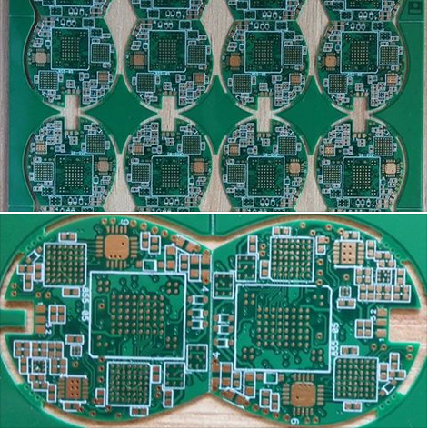
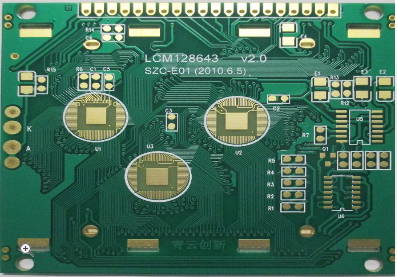
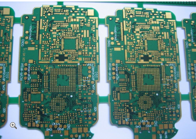
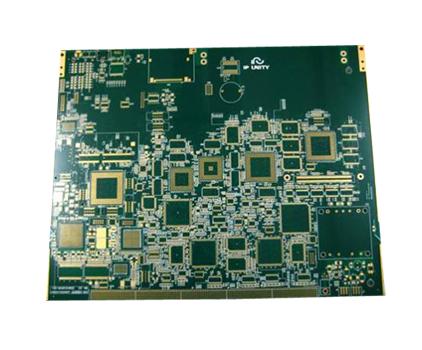
In the rapidly evolving field of aerospace technology, the demand for reliable, high-speed communication and precise radar systems has never been greater. At the heart of these advanced systems lies a critical enabling technology: High Frequency Microwave Printed Circuit Board (PCB) technology. This specialized discipline focuses on designing and manufacturing circuit boards that can efficiently operate at microwave frequencies, typically ranging from 1 GHz to over 100 GHz. For aerospace applications, where performance, weight, and reliability are paramount, the role of microwave PCBs is indispensable. They form the foundation of radar systems for navigation and threat detection, satellite communication links, and electronic warfare systems. The unique challenges of the aerospace environment—including extreme temperatures, intense vibration, and radiation—require PCBs that are not only electrically superior but also exceptionally robust. This article delves into the key aspects of this sophisticated technology, exploring the materials, design principles, manufacturing intricacies, and testing protocols that make high-frequency microwave PCBs a cornerstone of modern aerospace innovation.
Critical Material Selection for Superior Performance
The foundation of any high-frequency PCB is its substrate material. Unlike standard FR-4 boards used in consumer electronics, microwave PCBs for aerospace require materials with meticulously controlled dielectric properties. The dielectric constant (Dk) and dissipation factor (Df) are of utmost importance. A stable and low Dk is crucial for maintaining consistent signal velocity and impedance control across the board, which directly impacts signal integrity. A low Df is equally critical, as it minimizes signal loss, or insertion loss, which becomes significantly pronounced at higher frequencies. Materials like Polytetrafluoroethylene (PTFE) based laminates (e.g., Rogers RO4000® series, Taconic TLY®) are commonly chosen for their excellent high-frequency characteristics.
Beyond electrical properties, the thermal and mechanical stability of the substrate is non-negotiable for aerospace applications. These PCBs must withstand thermal cycling from -55°C to +125°C and beyond without delaminating or experiencing significant dimensional change. The coefficient of thermal expansion (CTE) of the substrate must be carefully matched to that of the copper layers to prevent cracking of plated through-holes during temperature fluctuations. Furthermore, materials must exhibit low moisture absorption to prevent degradation of electrical properties in humid conditions. The selection process is therefore a complex balance of electrical performance, thermal management, and long-term reliability under harsh operating conditions.
Precision Design and Signal Integrity Management
The design phase of a high-frequency microwave PCB is where performance is fundamentally architected. At microwave frequencies, PCB traces no longer behave as simple conductors but as transmission lines. Controlled impedance is the golden rule; every trace must be designed to a specific characteristic impedance (typically 50 or 75 ohms) to prevent signal reflections that degrade performance. This requires precise calculation of trace width, which is a function of the substrate's dielectric constant and thickness. Advanced electromagnetic simulation software is used extensively to model signal behavior, predict losses, and optimize the layout before any physical prototype is built.
Another critical design consideration is the management of electromagnetic interference (EMI) and crosstalk. As frequencies increase, radiation from traces becomes more significant, potentially interfering with nearby components. Careful grounding strategies, such as the use of continuous ground planes and via fencing around sensitive transmission lines, are employed to contain electromagnetic fields. The physical geometry of the board, including bends and transitions, must be optimized to minimize discontinuities. For complex multilayer boards, the arrangement of signal, ground, and power planes is critical for providing clear return paths and shielding sensitive signals from noise, ensuring the overall system meets stringent aerospace electromagnetic compatibility (EMC) standards.
Advanced Manufacturing and Fabrication Techniques
The fabrication of microwave PCBs demands a level of precision far exceeding that of conventional circuit boards. One of the most critical processes is etching. The accuracy of the etched trace dimensions directly defines the controlled impedance. Any under-etching or over-etching can alter the trace width, leading to impedance mismatches and signal integrity issues. State-of-the-art etching techniques with tight process controls are essential to achieve the required tolerances. Similarly, the laminate thickness must be held to very tight specifications, as variations will alter the impedance calculations.
Plated through-holes (PTHs) and vias present another manufacturing challenge. For high-frequency signals, a via is not just an electrical connection but a discontinuity in the transmission line that can cause reflections. The aspect ratio of these vias must be controlled, and techniques like back-drilling are often used to remove the unused portion of via barrels (stubs) that can act as resonant antennas, degrading signal quality at high frequencies. Surface finish is also crucial; choices like Electroless Nickel Immersion Gold (ENIG) are preferred for their flat surface, which is ideal for soldering fine-pitch components and ensuring reliable RF performance. The entire manufacturing process is conducted in a controlled environment to prevent contamination that could affect the material's dielectric properties.
Rigorous Testing and Quality Assurance for Reliability
Given the critical nature of aerospace systems, microwave PCBs undergo exhaustive testing and quality assurance protocols. Electrical testing begins with Time-Domain Reflectometry (TDR) to accurately measure the characteristic impedance of transmission lines and identify any imperfections or discontinuities. Vector Network Analyzers (VNAs) are used to measure key scattering (S) parameters, such as insertion loss and return loss, across the entire operating frequency band. These tests validate that the fabricated board performs as simulated during the design phase.
Beyond electrical performance, the boards are subjected to a battery of environmental and reliability tests that simulate the harsh conditions of aerospace operation. These include thermal shock cycling, where the board is rapidly moved between extreme hot and cold chambers to test the integrity of the materials and plated through-holes. Vibration and mechanical shock tests ensure the assembly can withstand the forces of launch and operation. Additionally, tests for moisture resistance and chemical exposure are standard. This rigorous validation process ensures that every microwave PCB deployed in an aerospace radar or communication system will perform reliably throughout its intended service life, where failure is not an option.
REPORT


