-
 Agriculture
-
 Health-Care
-
 Environment
-
 Construction-Real-Estate
-
 Tools-Hardware
-
 Home-Garden
-
 Furniture
-
 Luggage-Bags-Cases
-
 Medical-devices-Supplies
-
 Gifts-Crafts
-
 Sports-Entertainment
-
 Food-Beverage
-
 Vehicles-Transportation
-
 Power-Transmission
-
 Material-Handling
-
 Renewable-Energy
-
 Safety
-
 Testing-Instrument-Equipment
-
 Construction-Building-Machinery
-
 Pet-Supplies
-
 Personal-Care-Household-Cleaning
-
 Vehicle-Accessories-Electronics-Tools
-
 School-Office-Supplies
-
 Packaging-Printing
-
 Mother-Kids-Toys
-
 Business-Services
-
 Commercial-Equipment-Machinery
-
 Apparel-Accessories
-
 Security
-
 Shoes-Accessories
-
 Vehicle-Parts-Accessories
-
 Jewelry-Eyewear-Watches-Accessories
-
 Lights-Lighting
-
 Fabric-Textile-Raw-Material
-
 Fabrication-Services
-
 Industrial-Machinery
-
 Consumer-Electronics
-
 Electrical-Equipment-Supplies
-
 Electronic-Components-Accessories-Telecommunications
-
 Home-Appliances
-
 Beauty
-
 Chemicals
-
 Rubber-Plastics
-
 Metals-Alloys
- Masonry Materials
- Curtain Walls & Accessories
- Earthwork Products
- Fireproofing Materials
- Heat Insulation Materials
- Plastic Building Materials
- Building Boards
- Soundproofing Materials
- Timber
- Waterproofing Materials
- Balustrades & Handrails
- Bathroom & Kitchen
- Flooring & Accessories
- Tiles & Accessories
- Door, Window & Accessories
- Fireplaces & Stoves
- Floor Heating Systems & Parts
- Stairs & Stair Parts
- Ceilings
- Elevators & Escalators
- Stone
- Countertops, Vanity Tops & Table Tops
- Mosaics
- Metal Building Materials
- Multifunctional Materials
- Ladders & Scaffoldings
- Mouldings
- Corner Guards
- Decorative Films
- Formwork
- Building & Industrial Glass
- Other Construction & Real Estate
- Wallpapers/Wall panels
- HVAC System & Parts
- Outdoor Facilities
- Prefabricated Buildings
- Festive & Party Supplies
- Bathroom Products
- Household Sundries
- Rain Gear
- Garden Supplies
- Household Cleaning Tools & Accessories
- Lighters & Smoking Accessories
- Home Storage & Organization
- Household Scales
- Smart Home Improvement
- Home Textiles
- Kitchenware
- Drinkware & Accessories
- Dinnerware, Coffee & Wine
- Home Decor
- Golf
- Fitness & Body Building
- Amusement Park Facilities
- Billiards, Board Game,Coin Operated Games
- Musical Instruments
- Outdoor Affordable Luxury Sports
- Camping & Hiking
- Fishing
- Sports Safety&Rehabilitation
- Ball Sports Equipments
- Water Sports
- Winter Sports
- Luxury Travel Equipments
- Sports Shoes, Bags & Accessories
- Cycling
- Other Sports & Entertainment Products
- Artificial Grass&Sports Flooring&Sports Court Equipment
- Scooters
- Food Ingredients
- Honey & Honey Products
- Snacks
- Nuts & Kernels
- Seafood
- Plant & Animal Oil
- Beverages
- Fruit & Vegetable Products
- Frog & Escargot
- Bean Products
- Egg Products
- Dairy Products
- Seasonings & Condiments
- Canned Food
- Instant Food
- Baked Goods
- Other Food & Beverage
- Meat & Poultry
- Confectionery
- Grain Products
- Feminie Care
- Hair Care & Styling
- Body Care
- Hands & Feet Care
- Hygiene Products
- Men's Grooming
- Laundry Cleaning Supplies
- Travel Size & Gift Sets
- Room Deodorizers
- Other Personal Care Products
- Pest Control Products
- Special Household Cleaning
- Floor Cleaning
- Kitchen & Bathroom Cleaning
- Oral Care
- Bath Supplies
- Yellow Pages
- Correction Supplies
- Office Binding Supplies
- Office Cutting Supplies
- Board Erasers
- Office Adhesives & Tapes
- Education Supplies
- Pencil Cases & Bags
- Notebooks & Writing Pads
- File Folder Accessories
- Calendars
- Writing Accessories
- Commercial Office Supplies
- Pencil Sharpeners
- Pens
- Letter Pad/Paper
- Paper Envelopes
- Desk Organizers
- Pencils
- Markers & Highlighters
- Filing Products
- Art Supplies
- Easels
- Badge Holder & Accessories
- Office Paper
- Printer Supplies
- Book Covers
- Other Office & School Supplies
- Stationery Set
- Boards
- Clipboards
- Stamps
- Drafting Supplies
- Stencils
- Electronic Dictionary
- Books
- Map
- Magazines
- Calculators
- Baby & Toddler Toys
- Educational Toys
- Classic Toys
- Dress Up & Pretend Play
- Toy Vehicle
- Stuffed Animals & Plush Toys
- Outdoor Toys & Structures
- Balloons & Accessories
- Baby Food
- Children's Clothing
- Baby Supplies & Products
- Maternity Clothes
- Kids Shoes
- Baby Care
- Novelty & Gag Toys
- Dolls & Accessories
- Puzzle & Games
- Blocks & Model Building Toys
- Toddler Clothing
- Baby Clothing
- Kids' Luggage & Bags
- Arts, Crafts & DIY Toys
- Action & Toy Figures
- Baby Appliances
- Hobbies & Models
- Remote Control Toys
- Promotional Toys
- Pregnancy & Maternity
- Hygiene Products
- Kid's Textile&Bedding
- Novelty & Special Use
- Toy Weapons
- Baby Gifts
- Baby Storage & Organization
- Auto Drive Systems
- ATV/UTV Parts & Accessories
- Marine Parts & Accessories
- Other Auto Parts
- Trailer Parts & Accessories
- Auto Transmission Systems
- Train Parts & Accessories
- Universal Parts
- Railway Parts & Accessories
- Auto Brake Systems
- Aviation Parts & Accessories
- Truck Parts & Accessories
- Auto Suspension Systems
- Auto Lighting Systems
- New Energy Vehicle Parts & Accessories
- Auto Steering Systems
- Wheels, Tires & Accessories
- Bus Parts & Accessories
- Auto Performance Parts
- Cooling System
- Go-Kart & Kart Racer Parts & Accessories
- Air Conditioning Systems
- Heavy Duty Vehicle Parts & Accessories
- Auto Electrical Systems
- Auto Body Systems
- Auto Engine Systems
- Container Parts & Accessories
- Motorcycle Parts & Accessories
- Refrigeration & Heat Exchange Equipment
- Machine Tool Equipment
- Food & Beverage Machinery
- Agricultural Machinery & Equipment
- Apparel & Textile Machinery
- Chemical Machinery
- Packaging Machines
- Paper Production Machinery
- Plastic & Rubber Processing Machinery
- Industrial Robots
- Electronic Products Machinery
- Metal & Metallurgy Machinery
- Woodworking Machinery
- Home Product Manufacturing Machinery
- Machinery Accessories
- Environmental Machinery
- Machinery Service
- Electrical Equipment Manufacturing Machinery
- Industrial Compressors & Parts
- Tobacco & Cigarette Machinery
- Production Line
- Used Industrial Machinery
- Electronics Production Machinery
- Other Machinery & Industrial Equipment
- Camera, Photo & Accessories
- Portable Audio, Video & Accessories
- Television, Home Audio, Video & Accessories
- Video Games & Accessories
- Mobile Phone & Accessories
- Electronic Publications
- Earphone & Headphone & Accessories
- Speakers & Accessories
- Smart Electronics
- TV Receivers & Accessories
- Mobile Phone & Computer Repair Parts
- Chargers, Batteries & Power Supplies
- Used Electronics
- VR, AR, MR Hardware & Software
- Projectors & Presentation Equipments
- Other Consumer Electronics
- Cables & Commonly Used Accessories
- Computer Hardware & Software
- Displays, Signage and Optoelectronics
- Discrete Semiconductors
- Wireless & IoT Module and Products
- Telecommunications
- Connectors, Terminals & Accessories
- Development Boards, Electronic Modules and Kits
- Circuit Protection
- Sensors
- Isolators
- Audio Components and Products
- Integrated Circuits
- Power Supplies
- Relays
- RF, Microwave and RFID
- Electronic Accessories & Supplies
- Passive Components
- PCB & PCBA
- Air Quality Appliances
- Home Appliance Parts
- Heating & Cooling Appliances
- Small Kitchen Appliances
- Laundry Appliances
- Water Heaters
- Water Treatment Appliances
- Refrigerators & Freezers
- Personal Care & Beauty Appliances
- Major Kitchen Appliances
- Cleaning Appliances
- Second-hand Appliances
- Smart Home Appliances
- Other Home Appliances
- Energy Chemicals
- Inorganic Chemicals
- Basic Organic Chemicals
- Agrochemicals
- Admixture & Additives
- Catalysts & Chemical Auxiliary Agents
- Pigments & Dyestuff
- Coating & Paint
- Daily Chemicals
- Polymer
- Organic Intermediate
- Adhesives & Sealants
- Chemical Waste
- Biological Chemical Products
- Surface Treatment Chemicals
- Painting & Coating
- Chemical Reagents
- Flavor & Fragrance
- Non-Explosive Demolition Agents
- Other Chemicals
- Custom Chemical Services
Multilayer PCB Manufacturing Techniques for Enhanced Circuit Density and Reliability
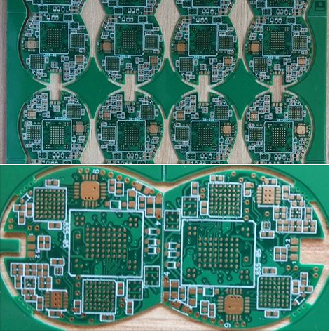
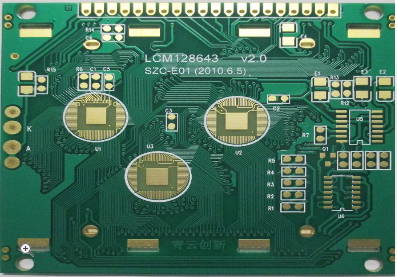
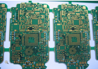
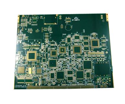
In the rapidly evolving world of electronics, the demand for compact, high-performance devices has driven innovations in printed circuit board (PCB) technology. Multilayer PCBs have emerged as a cornerstone of modern electronic design, enabling enhanced circuit density and reliability in applications ranging from smartphones to aerospace systems. Unlike single or double-layer boards, multilayer PCBs consist of multiple conductive layers separated by insulating materials, allowing for complex interconnections in a reduced footprint. This article delves into the advanced manufacturing techniques that make these high-density, reliable boards possible, exploring how they address challenges such as signal integrity, thermal management, and mechanical stability. By understanding these methods, engineers and designers can push the boundaries of what's achievable in electronics, paving the way for smarter, more efficient technologies.
Material Selection and Layer Stackup
The foundation of any multilayer PCB lies in the careful selection of materials and the design of the layer stackup. High-performance laminates, such as FR-4, polyimide, or ceramic-filled substrates, are chosen based on factors like thermal stability, dielectric constant, and loss tangent. For instance, in high-frequency applications, materials with low dielectric constants minimize signal attenuation, while those with high glass transition temperatures (Tg) ensure reliability under thermal stress. The stackup configuration, which defines the arrangement of conductive and insulating layers, is critical for impedance control and electromagnetic compatibility. A well-planned stackup can reduce crosstalk and improve signal integrity by providing dedicated ground and power planes.
Moreover, the use of advanced materials like halogen-free laminates supports environmental sustainability without compromising performance. In multilayer designs, the thickness of each layer must be precisely controlled to maintain uniformity and prevent issues like delamination. By optimizing material properties and stackup geometry, manufacturers can achieve higher circuit densities while enhancing the board's overall durability and electrical performance, making it suitable for demanding environments such as automotive or industrial systems.
Lamination and Bonding Processes
Lamination is a pivotal step in multilayer PCB manufacturing, where individual layers are bonded together under heat and pressure to form a solid, unified board. This process begins with the preparation of inner layers, which are coated with a semi-cured epoxy resin known as prepreg. The layers are then aligned using registration pins to ensure precise layer-to-layer connectivity, crucial for high-density interconnects (HDI). During lamination, the stack is subjected to controlled temperature and pressure cycles, causing the prepreg to flow and cure, thereby bonding the layers securely. Advanced techniques like vacuum lamination are employed to eliminate air pockets and voids, which could lead to electrical failures or reduced reliability.
In addition to traditional methods, sequential lamination is used for complex designs with buried or blind vias, allowing for multiple lamination cycles to build up the board gradually. This approach enhances circuit density by enabling more routing channels in a compact space. Post-lamination, the board undergoes curing to stabilize the bond, ensuring it can withstand mechanical stresses and thermal cycling. By refining lamination parameters, such as pressure profiles and temperature ramps, manufacturers can produce multilayer PCBs with improved layer adhesion and minimal warpage, directly contributing to long-term reliability in applications like medical devices or communication infrastructure.
Drilling and Via Formation
Drilling and via formation are essential for creating electrical connections between layers in a multilayer PCB. Mechanical drilling, using precision CNC machines, is commonly employed for through-hole vias, but for high-density designs, laser drilling has become the preferred method. Laser systems, such as CO2 or UV lasers, can produce microvias with diameters as small as 50 micrometers, allowing for greater routing flexibility and reduced layer count. These microvias are often used in HDI boards to connect adjacent layers, minimizing signal path lengths and improving electrical performance. After drilling, the vias are plated with copper to establish conductivity, a process that requires meticulous control to avoid defects like voids or insufficient plating.
Furthermore, advanced via structures, such as blind vias (connecting outer layers to inner layers) and buried vias (connecting only inner layers), enable more efficient use of board space. Techniques like via-in-pad design, where vias are placed directly under component pads, further enhance density by reducing the footprint of interconnections. However, this requires careful filling and planarization to ensure reliable solder joints. By integrating laser drilling with electroplating and filling processes, manufacturers can achieve superior via reliability, reducing the risk of thermal fatigue and increasing the overall lifespan of the PCB in high-stress environments.
Surface Finishes and Final Treatments
Surface finishes play a crucial role in protecting the copper traces and ensuring solderability in multilayer PCBs. Common finishes include HASL (Hot Air Solder Leveling), ENIG (Electroless Nickel Immersion Gold), and OSP (Organic Solderability Preservative), each offering distinct advantages. For high-density boards, ENIG is often preferred due to its flat surface, which facilitates fine-pitch component assembly, and its excellent corrosion resistance. The process involves depositing a thin layer of nickel followed by a gold layer, providing a reliable interface for soldering while preventing oxidation. Alternatively, immersion silver or tin finishes are used for their cost-effectiveness and good electrical performance.
In addition to surface finishes, final treatments such as solder mask application and silkscreen printing are applied to insulate the board and provide labeling. Advanced solder mask materials, like liquid photoimageable (LPI) masks, offer high resolution for covering tight spaces between traces, reducing the risk of short circuits. Electrical testing, including flying probe or bed-of-nails tests, is conducted to verify connectivity and identify any manufacturing defects. By combining robust surface finishes with comprehensive testing, manufacturers ensure that multilayer PCBs meet stringent quality standards, delivering enhanced reliability for end-users in sectors like consumer electronics or automotive systems.
REPORT


