







-
 Agriculture
-
 Health-Care
-
 Environment
-
 Construction-Real-Estate
-
 Tools-Hardware
-
 Home-Garden
-
 Furniture
-
 Luggage-Bags-Cases
-
 Medical-devices-Supplies
-
 Gifts-Crafts
-
 Sports-Entertainment
-
 Food-Beverage
-
 Vehicles-Transportation
-
 Power-Transmission
-
 Material-Handling
-
 Renewable-Energy
-
 Safety
-
 Testing-Instrument-Equipment
-
 Construction-Building-Machinery
-
 Pet-Supplies
-
 Personal-Care-Household-Cleaning
-
 Vehicle-Accessories-Electronics-Tools
-
 School-Office-Supplies
-
 Packaging-Printing
-
 Mother-Kids-Toys
-
 Business-Services
-
 Commercial-Equipment-Machinery
-
 Apparel-Accessories
-
 Security
-
 Shoes-Accessories
-
 Vehicle-Parts-Accessories
-
 Jewelry-Eyewear-Watches-Accessories
-
 Lights-Lighting
-
 Fabric-Textile-Raw-Material
-
 Fabrication-Services
-
 Industrial-Machinery
-
 Consumer-Electronics
-
 Electrical-Equipment-Supplies
-
 Electronic-Components-Accessories-Telecommunications
-
 Home-Appliances
-
 Beauty
-
 Chemicals
-
 Rubber-Plastics
-
 Metals-Alloys

























































































































































































































































































































































- Masonry Materials
- Curtain Walls & Accessories
- Earthwork Products
- Fireproofing Materials
- Heat Insulation Materials
- Plastic Building Materials
- Building Boards
- Soundproofing Materials
- Timber
- Waterproofing Materials
- Balustrades & Handrails
- Bathroom & Kitchen
- Flooring & Accessories
- Tiles & Accessories
- Door, Window & Accessories
- Fireplaces & Stoves
- Floor Heating Systems & Parts
- Stairs & Stair Parts
- Ceilings
- Elevators & Escalators
- Stone
- Countertops, Vanity Tops & Table Tops
- Mosaics
- Metal Building Materials
- Multifunctional Materials
- Ladders & Scaffoldings
- Mouldings
- Corner Guards
- Decorative Films
- Formwork
- Building & Industrial Glass
- Other Construction & Real Estate
- Wallpapers/Wall panels
- HVAC System & Parts
- Outdoor Facilities
- Prefabricated Buildings
- Festive & Party Supplies
- Bathroom Products
- Household Sundries
- Rain Gear
- Garden Supplies
- Household Cleaning Tools & Accessories
- Lighters & Smoking Accessories
- Home Storage & Organization
- Household Scales
- Smart Home Improvement
- Home Textiles
- Kitchenware
- Drinkware & Accessories
- Dinnerware, Coffee & Wine
- Home Decor
- Golf
- Fitness & Body Building
- Amusement Park Facilities
- Billiards, Board Game,Coin Operated Games
- Musical Instruments
- Outdoor Affordable Luxury Sports
- Camping & Hiking
- Fishing
- Sports Safety&Rehabilitation
- Ball Sports Equipments
- Water Sports
- Winter Sports
- Luxury Travel Equipments
- Sports Shoes, Bags & Accessories
- Cycling
- Other Sports & Entertainment Products
- Artificial Grass&Sports Flooring&Sports Court Equipment
- Scooters
- Food Ingredients
- Honey & Honey Products
- Snacks
- Nuts & Kernels
- Seafood
- Plant & Animal Oil
- Beverages
- Fruit & Vegetable Products
- Frog & Escargot
- Bean Products
- Egg Products
- Dairy Products
- Seasonings & Condiments
- Canned Food
- Instant Food
- Baked Goods
- Other Food & Beverage
- Meat & Poultry
- Confectionery
- Grain Products
- Feminie Care
- Hair Care & Styling
- Body Care
- Hands & Feet Care
- Hygiene Products
- Men's Grooming
- Laundry Cleaning Supplies
- Travel Size & Gift Sets
- Room Deodorizers
- Other Personal Care Products
- Pest Control Products
- Special Household Cleaning
- Floor Cleaning
- Kitchen & Bathroom Cleaning
- Oral Care
- Bath Supplies
- Yellow Pages
- Correction Supplies
- Office Binding Supplies
- Office Cutting Supplies
- Board Erasers
- Office Adhesives & Tapes
- Education Supplies
- Pencil Cases & Bags
- Notebooks & Writing Pads
- File Folder Accessories
- Calendars
- Writing Accessories
- Commercial Office Supplies
- Pencil Sharpeners
- Pens
- Letter Pad/Paper
- Paper Envelopes
- Desk Organizers
- Pencils
- Markers & Highlighters
- Filing Products
- Art Supplies
- Easels
- Badge Holder & Accessories
- Office Paper
- Printer Supplies
- Book Covers
- Other Office & School Supplies
- Stationery Set
- Boards
- Clipboards
- Stamps
- Drafting Supplies
- Stencils
- Electronic Dictionary
- Books
- Map
- Magazines
- Calculators
- Baby & Toddler Toys
- Educational Toys
- Classic Toys
- Dress Up & Pretend Play
- Toy Vehicle
- Stuffed Animals & Plush Toys
- Outdoor Toys & Structures
- Balloons & Accessories
- Baby Food
- Children's Clothing
- Baby Supplies & Products
- Maternity Clothes
- Kids Shoes
- Baby Care
- Novelty & Gag Toys
- Dolls & Accessories
- Puzzle & Games
- Blocks & Model Building Toys
- Toddler Clothing
- Baby Clothing
- Kids' Luggage & Bags
- Arts, Crafts & DIY Toys
- Action & Toy Figures
- Baby Appliances
- Hobbies & Models
- Remote Control Toys
- Promotional Toys
- Pregnancy & Maternity
- Hygiene Products
- Kid's Textile&Bedding
- Novelty & Special Use
- Toy Weapons
- Baby Gifts
- Baby Storage & Organization
- Auto Drive Systems
- ATV/UTV Parts & Accessories
- Marine Parts & Accessories
- Other Auto Parts
- Trailer Parts & Accessories
- Auto Transmission Systems
- Train Parts & Accessories
- Universal Parts
- Railway Parts & Accessories
- Auto Brake Systems
- Aviation Parts & Accessories
- Truck Parts & Accessories
- Auto Suspension Systems
- Auto Lighting Systems
- New Energy Vehicle Parts & Accessories
- Auto Steering Systems
- Wheels, Tires & Accessories
- Bus Parts & Accessories
- Auto Performance Parts
- Cooling System
- Go-Kart & Kart Racer Parts & Accessories
- Air Conditioning Systems
- Heavy Duty Vehicle Parts & Accessories
- Auto Electrical Systems
- Auto Body Systems
- Auto Engine Systems
- Container Parts & Accessories
- Motorcycle Parts & Accessories
- Refrigeration & Heat Exchange Equipment
- Machine Tool Equipment
- Food & Beverage Machinery
- Agricultural Machinery & Equipment
- Apparel & Textile Machinery
- Chemical Machinery
- Packaging Machines
- Paper Production Machinery
- Plastic & Rubber Processing Machinery
- Industrial Robots
- Electronic Products Machinery
- Metal & Metallurgy Machinery
- Woodworking Machinery
- Home Product Manufacturing Machinery
- Machinery Accessories
- Environmental Machinery
- Machinery Service
- Electrical Equipment Manufacturing Machinery
- Industrial Compressors & Parts
- Tobacco & Cigarette Machinery
- Production Line
- Used Industrial Machinery
- Electronics Production Machinery
- Other Machinery & Industrial Equipment
- Camera, Photo & Accessories
- Portable Audio, Video & Accessories
- Television, Home Audio, Video & Accessories
- Video Games & Accessories
- Mobile Phone & Accessories
- Electronic Publications
- Earphone & Headphone & Accessories
- Speakers & Accessories
- Smart Electronics
- TV Receivers & Accessories
- Mobile Phone & Computer Repair Parts
- Chargers, Batteries & Power Supplies
- Used Electronics
- VR, AR, MR Hardware & Software
- Projectors & Presentation Equipments
- Other Consumer Electronics
- Cables & Commonly Used Accessories
- Computer Hardware & Software
- Displays, Signage and Optoelectronics
- Discrete Semiconductors
- Wireless & IoT Module and Products
- Telecommunications
- Connectors, Terminals & Accessories
- Development Boards, Electronic Modules and Kits
- Circuit Protection
- Sensors
- Isolators
- Audio Components and Products
- Integrated Circuits
- Power Supplies
- Relays
- RF, Microwave and RFID
- Electronic Accessories & Supplies
- Passive Components
- PCB & PCBA
- Air Quality Appliances
- Home Appliance Parts
- Heating & Cooling Appliances
- Small Kitchen Appliances
- Laundry Appliances
- Water Heaters
- Water Treatment Appliances
- Refrigerators & Freezers
- Personal Care & Beauty Appliances
- Major Kitchen Appliances
- Cleaning Appliances
- Second-hand Appliances
- Smart Home Appliances
- Other Home Appliances
- Energy Chemicals
- Inorganic Chemicals
- Basic Organic Chemicals
- Agrochemicals
- Admixture & Additives
- Catalysts & Chemical Auxiliary Agents
- Pigments & Dyestuff
- Coating & Paint
- Daily Chemicals
- Polymer
- Organic Intermediate
- Adhesives & Sealants
- Chemical Waste
- Biological Chemical Products
- Surface Treatment Chemicals
- Painting & Coating
- Chemical Reagents
- Flavor & Fragrance
- Non-Explosive Demolition Agents
- Other Chemicals
- Custom Chemical Services

How to Communicate Complex Requirements for Custom Plastic Tooling
Clear communication is essential when developing custom plastic tooling, especially for parts with complex geometry, tight tolerances, or demanding cosmetic requirements. A complete tooling brief should explain the part's function, application, material, appearance, critical dimensions, production volume, mold expectations, inspection standards, and delivery needs. Drawings, 3D files, or physical samples should be included whenever possible so the tooling manufacturer can identify risks before mold construction begins.
What to Include in a Plastic Tooling Brief
Begin with the finished component rather than the mold itself. Describe how the part will be used, which surfaces are functional, where it will connect to other components, and which areas will remain visible. Mark important assembly interfaces, sealing surfaces, appearance zones, and dimensions that require special control.
- Part function, application, and assembly requirements
- Product geometry, wall thickness, draft, ribs, bosses, and other difficult features
- Resin type, color, texture, gloss level, and surface finish
- Critical dimensions, allowable tolerances, and inspection references
- Expected annual volume, total production quantity, and mold-life target
- Preferred mold materials, runner design, validation process, and delivery schedule
Connect Product Requirements to Mold Design
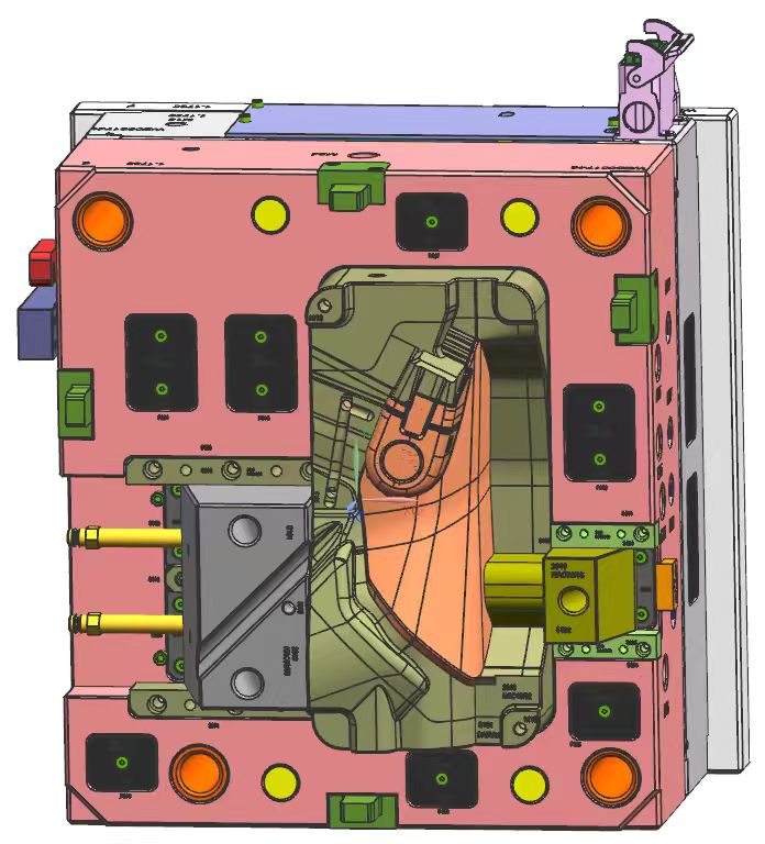
Once the part requirements are defined, connect them to the proposed mold architecture. Custom injection tooling may use an S50C or P20 mold base, with cavity steels such as 718H, 1.2738, or S136. The runner system can be configured as either cold runner or hot runner, depending on the resin, cycle requirements, gate location, cosmetic expectations, and production strategy.
Do not apply a general tolerance statement to every feature unless that is genuinely required. Identify the exact dimensions or interfaces that need close control. The available precision tooling specification supports tolerances down to +/-0.02 mm, but the manufacturer should know whether this target applies to selected critical features or to the complete part. The requested quantity also matters: prototype tooling, short-run production molds, and tools intended for long-term manufacturing may require different steel grades, cooling layouts, maintenance provisions, and inspection plans.
Describe Difficult Features with Specific Language
Terms such as “complex mold” or “high precision” are not sufficient on their own. Point out deep and narrow cavities, difficult parting lines, thin walls, alignment-sensitive interfaces, undercuts, inserts, overmolding, double-shot sections, and polished or textured cosmetic surfaces. Explain the risk associated with each feature, such as possible deformation, flash, sink marks, mismatch, weld lines, difficult ejection, or inconsistent filling.
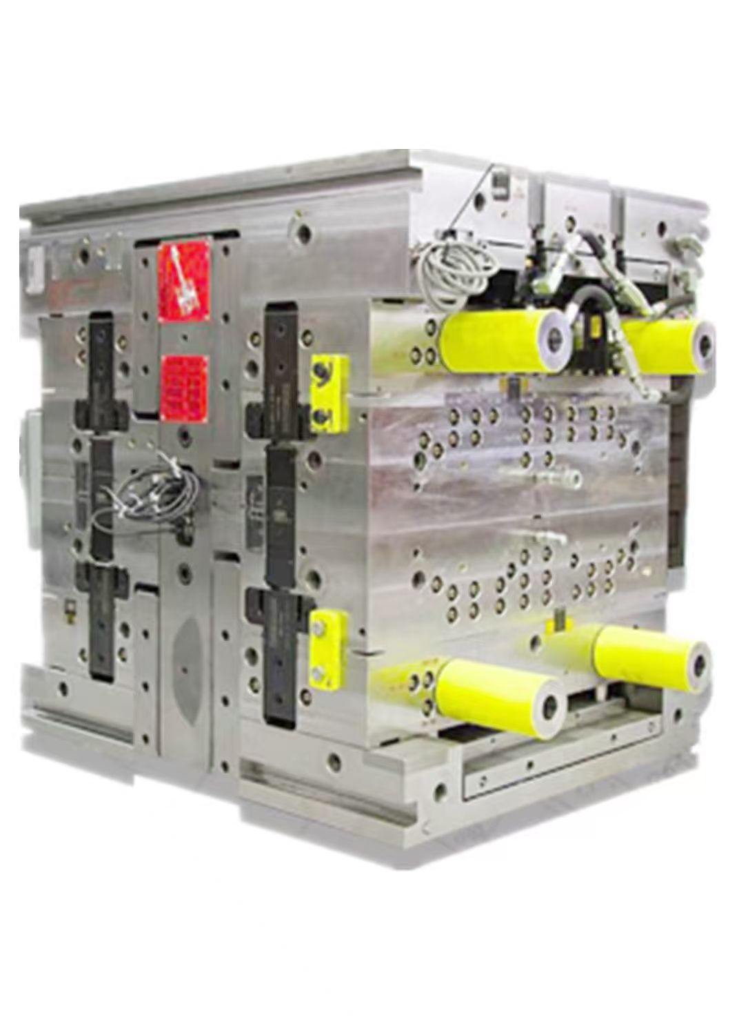
Longterm Mold supports injection mold structural design, precision CNC component development, sample verification, and molding process optimization. Its engineering team works from customer drawings or samples and uses UG, SolidWorks, and AutoCAD for development. Manufacturing resources include 3-axis and 5-axis CNC machining systems, supporting standard tooling as well as complex precision, double-shot, and overmolding projects.
Define How the Mold Will Be Approved
A tooling requirement is incomplete without an acceptance plan. State which dimensions will be checked, how appearance will be evaluated, how many trial cycles are expected, and whether samples must be approved before shipment. Available validation activities include mold trials, dimensional inspection, 3D inspection, CMM measurement, first article inspection, complete dimension reports, surface checks, and multi-cycle testing.
Each inspection method should be connected to a measurable requirement. For example, a CMM report may verify a critical assembly interface, while visual inspection can confirm texture, gloss, gate marks, and parting-line quality. For complex tools, require trial samples under agreed process conditions and specify which approved sample or report authorizes the next production step.
Match the Tooling Plan to the Application
Application information helps the mold maker select a practical design and validation method. Longterm Mold has handled electronic housing molds for handheld devices in Italy, double-shot overmolding molds for consumer electronics in France, home appliance component molds for a United States customer, and industrial equipment housing molds for an Australian customer. Project feedback has emphasized dimensional accuracy, surface quality, alignment, stable trial samples, technical support, and schedule performance.
Organize the final request into five sections: product and application details, geometry and tolerance data, mold construction preferences, validation and approval criteria, and delivery or after-sales requirements. This structure highlights open decisions before design starts and provides a shared reference for design review, machining, mold trials, sample approval, production, and future maintenance.
Tooling Requirement Comparison
| Requirement Area | Customer Information | Potential Tooling Solution |
|---|---|---|
| Materials and mold construction | Preferred mold base, cavity steel, runner system, resin, and surface finish | S50C or P20 mold base; 718H, 1.2738, or S136 cavity steel; cold-runner or hot-runner configuration |
| Accuracy and inspection | Critical features, tolerance limits, measurement method, and sample approval rules | Precision tolerance of +/-0.02 mm, supported by mold trials, dimensional inspection, and full pre-shipment inspection |
| Service scope | Whether the project covers tooling only or includes molded-part production | OEM mold making, tooling with injection molding, precision overmolding, or mold development followed by mass production |
| Complexity and durability | Geometry, alignment needs, double-shot requirements, production quantity, and expected service life | Standard, complex precision, double-shot, and overmolding tools with a typical life of 50,000 to 1,000,000 shots |
Frequently Asked Questions
What should be sent with a complex tooling inquiry?
Send a product drawing, 3D model, or physical sample together with the application, plastic resin, color and finish, critical dimensions, tolerance targets, production volume, preferred steel, runner preference, inspection standards, and delivery expectations. Clearly mark difficult geometry and alignment-sensitive areas.
What is the best way to communicate tight tolerances?
List the numerical tolerance and associate it with the relevant feature, datum, or interface. The available specification supports a precision tolerance of +/-0.02 mm. Also identify whether dimensional inspection, 3D measurement, CMM testing, or full inspection will be used for acceptance.
How can tooling compliance be verified before shipment?
Agree on mold trials, sample review, dimensional reporting, appearance inspection, and pre-shipment approval at the beginning of the project. Complex tools may also require multi-cycle trials and a first article inspection. Define the report or approved sample that permits shipment and production release.
Conclusion
The clearest plastic tooling requests translate product expectations into measurable engineering information. Provide drawings or samples, identify critical features, explain complex geometry, specify material and finish requirements, state tolerance and mold-life targets, and document the inspection and approval process. Longterm Mold provides tooling-only services, injection molding, precision double-shot and overmolding, and mold development with mass production. Its ISO 9001:2015 certification covers the design, manufacture, and sale of precision molds and plastic products. For technical assistance, contact rogerluo@longterm-mold.com.
About Longterm Mold
Longterm Manufacturing Solutions Limited was established in 2010 and serves customers in North America, Europe, Australia, and other international markets. The company has five R&D engineers specializing in molds and precision machining, with services covering mold design, tooling, precision machining, mold manufacturing, and plastic parts production. ISO 9001:2015 certification supports its quality system, while project experience includes electronics, home appliances, and industrial equipment.

REPORT